
we think about measurement
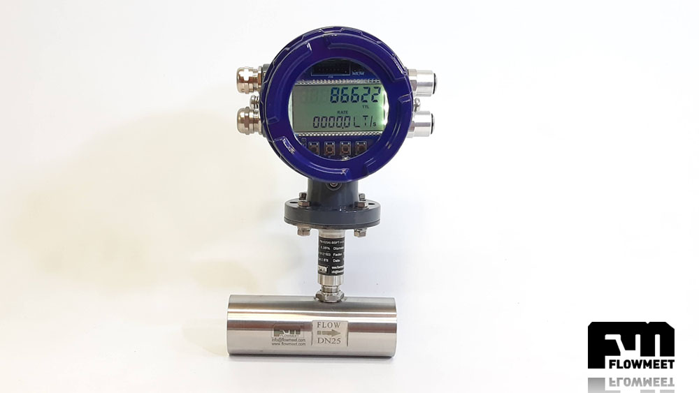
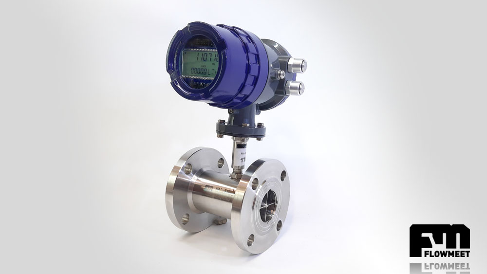
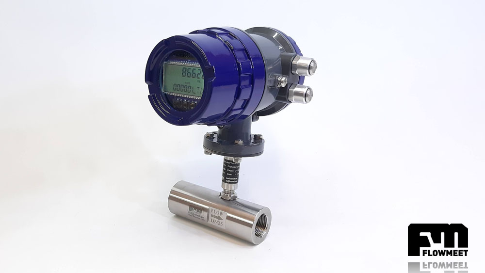
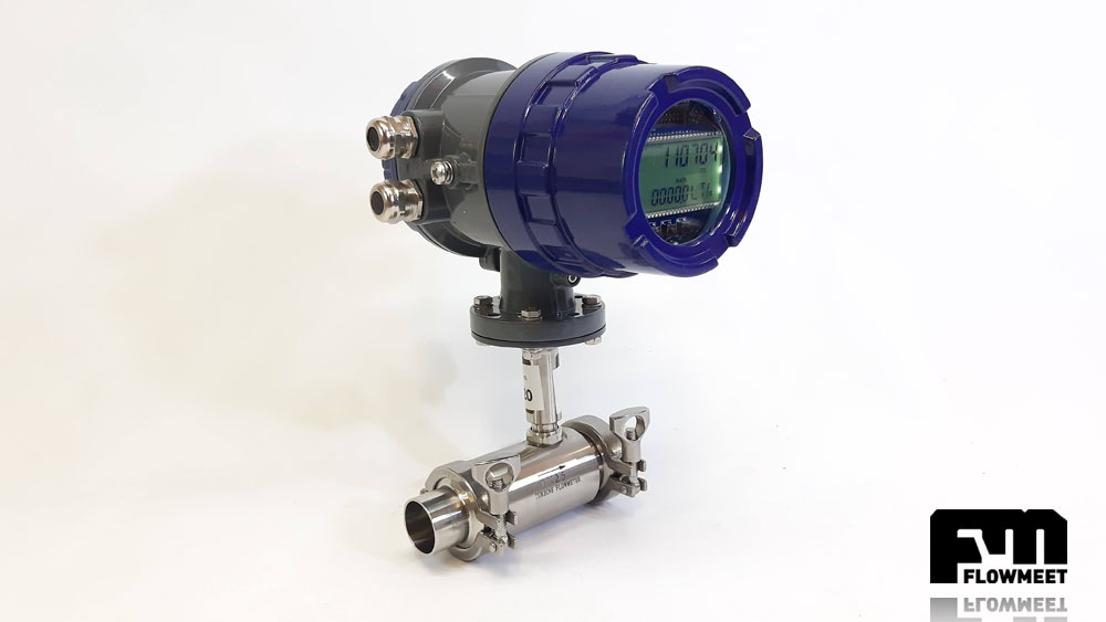
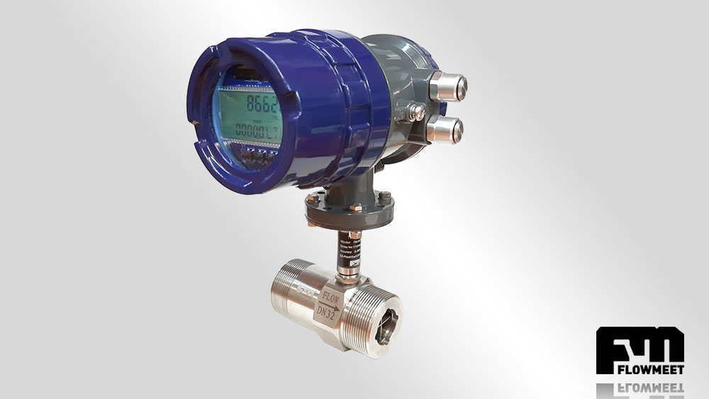
AI Series Turbine Flowmeter
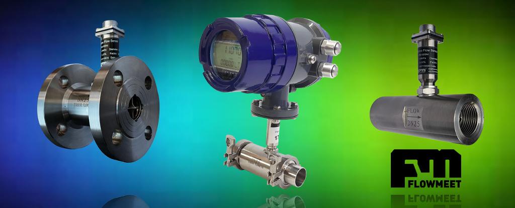
The FLOWMEET AI series full bore axial turbine flowmeters are the evolution of our AX series. The AX series for more than 15 years introduced more than 2,000 units to the market. This new series has a greater number of construction options in its rotor and body materials, more options for choosing a flow computer, connection processes, measurement specifications and communication protocols.
| 1/2" BSPT MACHO | 1/2" BSPT MACHO | 1/2" BSPT MACHO | 1" BSPT MACHO | 1" BSPT MACHO | 1" BSPT / BRIDA | 2" BSPT MACHO |
| 63 | 63 | 63 | 63 | 63 | 63 | 16 |
| 0.7 | 1.7 | 3.3 | 8 | 13 | 17 | 25 |
| 4 | 10 | 20 | 100 | 130 | 160 | 250 |
| 0.04 | 0.1 | 0.2 | 0.5 | 0.8 | 1 | 1.5 |
| 0.25 | 0.6 | 1.2 | 6 | 8 | 10 | 15 |
| 75 | 85 | 140 |
| 2" BSPT MACHO | 2" BSPT/ ASME-150 | 3" BSPT/ ASME-150 | 4" Brida ASME-150 | 6" Brida ASME-150 | 8" Brida ASME-150 |
| 63 | 63 | 63 | 15 | 15 | 15 |
| 30 | 60 | 160 | 330 | 500 | 1300 |
| 300 | 700 | 1600 | 3300 | 5000 | 14000 |
| 2 | 4 | 10 | 20 | 30 | 80 |
| 20 | 40 | 100 | 200 | 300 | 800 |
| 140 | 200/ |
Technical Data
- Non-linearity: better than 0.5% standard and 0.2% on request
- Repeatability: better than 0.05%
- Body: AISI-304L standard, 316 on request
- Rotor: AISI-440 standard and duplex on request
- Bushings / Bearings: tungsten carbide / AISI-316
- Lifespan: 80,000 hours at 80% higher maximum flow
- Connection processes: BST-T, NPT, ASME-150, ASME-300, ASME-600, ASME-900, ASME-1500
- Fluid temperature: minimum -20 ° C maximum 80 ° C normal range, -190 ° C to 120 ° C extended range
Common Applications
- Water with aggressive chemicals at high pressure
- Solvent plant
- Fuel reception and dispatch control
- Water, gas and oil separators
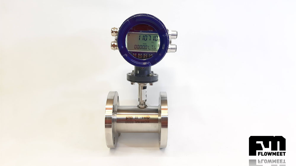
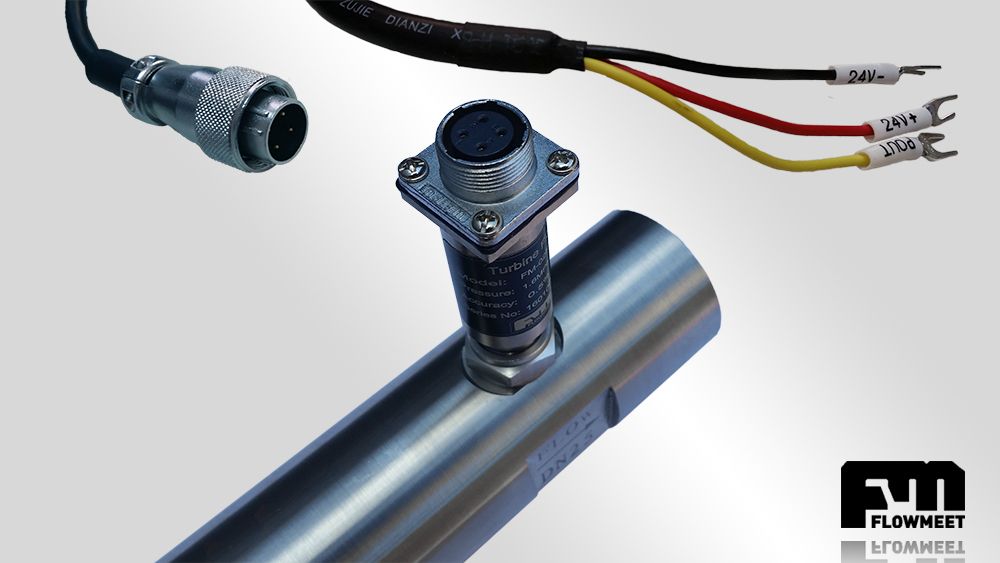
Operation of turbine flowmeters
Turbine flowmeters consist of a vane rotor, this is the only moving part, which rotates due to the flow in the pipe. The rotor design attempts to keep flow disturbance to a minimum, taking as little energy as possible from the moving fluid. The vanes cut the fluid in a helical shape. Each revolution of the rotor, given by the longitudinal advance of the fluid, is translated into a particular volume multiplied by a scale factor of each equipment. The errors in the measurement of this equipment are given by two factors: the mechanical traction effects (between the fluid and the meter components) and magnetic traction effects (which originate between a pick-up coil and the rotor blades). they are a source of error. In turn, the traction effects vary with the frequency of rotation of the turbine, for this reason they represent a source of non-linearity in the frequency-flow curve of the meter.