
we think about measurement
Installation and maintenance guide for a turbine

Turbine flowmeters
Summary: with FLOWMEET turbine meters you can obtain errors as low as 0.4%, even some clients claim to have a system with an error of less than 0.25%, to achieve this objective you must have a well-tuned system, the following This article deals with the correct installation and maintenance of the meter to get its maximum performance.
1. Meter inspection
Check that the rotor turns freely. If necessary, lubricate the bushings with a drop of light oil to do this test. The meter is shipped from the factory already lubricated. Be careful if you use compressed air, do not exceed the maximum speed of the rotor. This condition can deteriorate the bushings. Verify that the retention latches are properly installed. The tips of the same should go towards the inside of the meter, avoiding the rotation of the supports. Gather the information provided with your meter and verify that all the technical characteristics of the meter are compatible with the process (minimum and maximum flow; pressure and temperature range; compatibility of materials, body, internals, seals and other data if any).
2. Meter location
The different types of mounting architecture and accessories used in the pipes generate unwanted disturbances and turbulence when measuring the circulating flow. Sometimes these disturbances cause the angle of attack of the liquid jet on the rotor blades to differ with the calibration conditions in the factory and mainly when there are variations in flow. To this end, to ensure the correct operation of the meter, a minimum of ten straight pipe diameters must be provided before the meter and five after it. When the pipes incorporate accessories such as elbows, tees, reductions or valves, these dimensions will be greater. The figure indicates the minimum distances required for some typical cases.
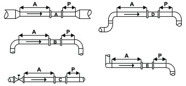
| A | B | C | D | E | |
| A | 10 | 15 | 50 | 20 | 30 |
| P | 5 | 5 | 5 | 5 | 5 |
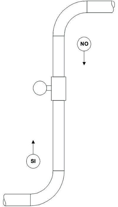
If you do not have the necessary distance, it is advisable to consult the factory on the particular case. The meter MUST NOT BE INSTALLED in the immediate vicinity of the pump, this distance should be as long as possible. Nor should it be installed near discharge outlets that do not ensure a minimum pressure drop at the meter outlet (approx. 0.2 bar), this will prevent the rotor from accelerating unduly. The meter will work correctly in horizontal pipes, and can also be applied in vertical pipes, only with upward flow. If the totalizer or transmitter unit is not placed on the meter, the primary signal of the turbine (millivolts a.c.) must be connected with a meshed instrument cable, to avoid noises of an electrical nature that could distort the measurement.
This distance should not exceed 20 to 30 meters in those meters whose signal at minimum flow is of the order of 20 mV. ef.
If in the installation area, there are possibilities of generating loud noises, such as transformers, motor or coil fields, contactors or relays, etc., which may incorporate pulses or cancel part or all of the turbine signal, it is advisable to use of a signal amplifier. Special care must be taken in those places where there are variable speed drives.
3. Recommendations
-
Caution should be exercised if the meter is used to count the unloading of trucks or tanks, since in the final stage, the generation of vortexes, it injects air bubbles that distort the measurement.
-
Best meter performance is achieved when normal operating flow is between 40% and 60% of range.
-
It is not advisable for the meter to operate very close to the minimum range, any variation in the default flow rate can take it out of range, causing an unwanted measurement error.
-
If you work with liquids whose density is lower than that of water, it is convenient to operate the meter above 20% of the minimum flow range.
-
For viscous liquids, consult the factory, sometimes, depending on the viscosity, the meter should be used above 40% of the minimum range.
-
The meter can work above 100% of the flow range, with a correct indication, but this condition will decrease the useful life of the bushings.
-
In the case of liquefied gases or highly volatile liquids, it must be ensured that the pressure inside the pipe is such that there is no gasification.
-
Make sure that there are no bubbles or pockets of air or gas in the pipe, this will cause an erroneous reading since everything is counted as liquid, and it will even decrease the useful life of the bushings.
-
When installing the sensing coil, it should be tightened by hand, until it stops at the bottom of the body thread, and then tighten the locknut with the appropriate wrench, without exerting excessive effort.
-
When the meter is flanged, check the correct centering of the gaskets when installing it and that they correspond to the series of flanges.
-
The design of the retention locks ensures a perfect anchoring of the meter's interior parts, being extremely simple to place and remove.
Check after operating them, that they are correctly positioned before installing the meter. -
With the signals transmitted to the control room, it is advisable to use meshed instrument pairs or triples.
4. Commissioning
When the pipes are new or have been out of service due to modifications, before installing the meter, it is advisable to circulate a sufficient quantity of liquid to wash the pipe and thus ensure that remains of slag, mechanical material or others, do not go to the meter, which may cause breakage or miscalibration. When the liquids are clean, the installation does not require the use of a previous filter. It is only necessary if it carries particles, threads or lint that could jam or damage the meter. The design of the pipe must be prepared so that there is no back flow of liquid. This does not affect the meter, but it will be counted as dispensed liquid. Verify that the meter inlet is in the correct direction and that the seals or gaskets are in place. If in doubt, remove the meter, check and install it again. Check that the nuts and threaded connections are securely fastened. Never leave valves or connections that by mistake or ignorance, could be opened causing accidents. Always install firmly attached plugs or caps.
Be very careful, in those pipes subject to vibrations, if necessary, taper the same to avoid them. With everything in condition, start the fluid circulation in a moderate way, until all the air is purged from the pipe; otherwise it will be computed as liquid. Avoid any water hammer due to the violent opening or closing of valves. Adjust the valves to the desired flow rate. Before leaving the meter running for good, check that there are no leaks.
5. Operation
The rotor blades or blades made of ferromagnetic stainless steel (thus 430), disturb the magnetic field of the pick-up coil, housed externally and mechanically isolated from the process, inducing pulses of variable frequency with the flow rate. These pulses are directly proportional to the speed of displacement of the liquid that circulates through the pipe (instantaneous flow), giving a constant value per unit of volume, called the K factor of the meter or simply the K factor.
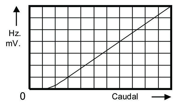
The pulses obtained can be applied directly to a 1000, 2000 series totalizer or conditioned for the management of registers, alarms, plc or automatic control loops. By applying the corresponding factor, it can be converted to other standard engineering units. The meter rotor needs a minimum speed to start rotating proportionally within the linear calibration range. Lower speeds will produce an uncertain and exponential error in the measurement, since the energy delivered to it is not enough to overcome the weight and friction of the same and sometimes it will rotate at uneven intervals. Make sure that the minimum circulating flow corresponds to the model of meter purchased.
6. Maintenance Routine
When the liquids are clean and free of impurities, such as lint, threads, or suspended solids, that can jam or damage the meter, it will work for long periods without having to be removed from the pipe. Generally a visual inspection of the rotor bushings can be performed, depending on the time interval, on the demands of your process. With the meter removed, check that the rotor turns freely, without friction, or has excessive precession.
Verify that the blades of the same are not damaged or twisted, decalibrating the meter.
CAUTION: If you use compressed air to rotate it, do not apply too much speed which could damage the bushings.
When removing the interior kit from the meter, it is advisable to always operate on the inlet lock, in case it was incorrectly installed by mistake, the interior kit will also be retained inside the body by the outlet lock. When reinstalling the inner kit, check that the direction of the indications (engraved letters and / or arrows) on the supports and the rotor coincide with the direction of flow. Verify that the retention latches are properly installed. The tips of the same should go towards the inside of the meter, avoiding the rotation of the supports.
7. Repair
If for any reason you remove the rotor, be sure to install it in the same position as it was calibrated at the factory. Installing it backwards may cause an error of approximately 1%, (typical of each meter). If the bushings or interior parts show any anomaly, you can purchase a replacement interior kit and replace it, and it is advisable to send the flowmeter to the factory for repair and correct calibration.
IMPORTANT: Before intervening the meter, notify your company's security department and take the necessary precautions.
Use tools and safety elements.
8. Fault Location.
A ) If the meter indicates a volume lower than the real one.
A-1 Verify that there is no false contact in the electrical connections.
A-2 Check that the rotor is not turning forcibly or slightly stuck.
B ) If the meter indicates excessive volume.
B-1 Verify that there is no gasification inside the pipe.
B-2 Check that the indicator is not picking up pulses from any external source.
C ) If the meter suddenly stopped working
C-1 Make sure there is liquid circulation in the pipe.
C-2 Verify that this flow is higher than the minimum of the meter.
C-3 Measure the resistance of the sensing coil with the tester; usually 1600 ohm. If there is no continuity, replace it.
C-4 Measure the ac millivolt signal with the tester, the indicated value must be within the values specified in the fabrication sheet of your flowmeter. Generally between 20 and 500 mV.ef. according to the model.
If there is no signal, the rotor is stuck or there is no fluid circulation.
If you got a signal, check your transmitter or reader unit.
9. Parameter Denomination
A) K FACTOR:
It is the meter factor expressed in pulses / liter.
Example: Pulses obtained in the counter = 10,400.
Volume of the standard element = 200 liters.
K = P = 10.400 = 52 Pulses / liter.
L 200
This value will be programmed in the totalizer (52 pulses / liter)
In case of using another engineering unit, the equivalent pulse value will be programmed:
Ej.: Liters = 52 pulses
M3 = 52.000 pulses
Gallons = 196,82 pulses
Note: The meter K-factor is generally obtained by averaging the values corresponding to 80% of the meter's largest flow range, and the initial 20% of the range absorbs most of the error.
B) MAXIMUM OPERATING FREQUENCY
The maximum operating frequency is equal to the maximum flow in liters per second, multiplied by the factor K.
Example: Turbine meter diam. 1 1/2 ".
Max. Flow Rate = 30 M3/h = 8,333 LPS
K Factor = 52 pulsos / litro.
Fmax.= LPSmax. x K = 8,333 x 52 = 433,3 Hz.
C) TOTALIZER COUNT CONTROL
The digit change time in the totalizer is equal to the K factor (in the programmed volume unit) divided by the input frequency.
Example: volume unit set M3.
K Factor 52.000 PPM3.
Input Frequency = 216 Hz. (50 % of range).
Digit change time for 1 M3 =
t = K = 52.000 = 240,74 Seconds.
F 216
D) INSTANT FLOW INDICATION CONTROL
The flow is equal to the displaced volume, divided by the elapsed time; Thus:
Knowing the digit change time, a practical way to determine the instantaneous flow rate is:
Qi = V = 1000 lts. = 4,1538 lts / sec = 14.954 lts / h = 14,95 m3/h
t 240,74 sec.
Knowing the input frequency and the K factor.
Qi = Hz = 216 = 4,1538 lts / sec = 14.954 lts/h = 14,95 M3 / h
K 52
E) CURRENT OUTPUT CONTROL (4-20 mA)
Maximum Flow Rate = 30 m3 / h = 20 mA.
Current Flow Rate = 14,954 m3 / h (approx. 50% of range)
Zero Flow = 4 mA.
Calculation:
I out = I max. * Q act. + 4 = 16 * 14,954 + 4 =
Q max. 30
I out = 11,975 mA.
Note: I max. are mA. of the working range
( 20 mA.– 4 mA. = 16 mA. )