
we think about measurement
DC Series Tanker Quick Joint Flowmeter
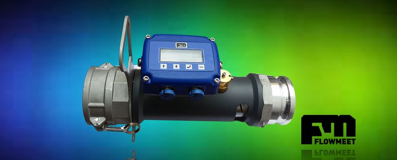
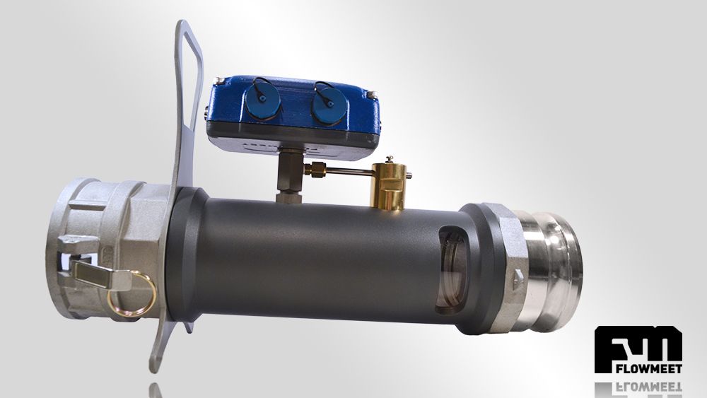
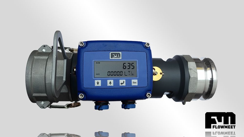
Control the unloading of a tanker truck with this one-of-a-kind flowmeter, directly coupled to the tanker, of the removable type. No modification of the structure of your cistern is necessary. It has a flow conditioner and flow detector to maximize the accuracy and precision of the measurement under discharge conditions. This instrument is aimed at information management, the download history is recorded detailing the data of each maneuver. The information can be collected with any phone with Android system (optional) or through a PC (optional). At the same time, it allows the printing of tickets (optional) for each operation carried out. It has anti-explosive certification for classified areas.
Special Features
-
FM-520 flow computer
-
Scheduling of sending e-mail with the information of the operations (optional)
-
Geopositioning data of the operations carried out (optional)
-
Ticket printing with portable printer (optional)
-
Download history available for download to Windows and Android (optional)
-
Anti-explosive certification for classified areas
Technical data
-
Vein Straightener (conditions fuel flow to reduce turbulence and improve metering)
-
Flow Detector (Reduces air flow count when tank empties)
-
Non-linearity: better than 0.25%
-
Repeatability: better than 0.2%
-
Body: Dur Aluminum T6061
-
Quick coupling to 3 ", 4" and 6 ''
Common Applications
-
Fuel dispatch and receipt control
-
Measurement of edible oil production
Turbine Flowmeter Operation
Turbine flowmeters consist of a vane rotor, this is the only moving part, which rotates due to the flow in the pipeline. The rotor design attempts to keep flow disturbance to a minimum, taking as little energy as possible from the moving fluid. The vanes cut the fluid in a helical shape. Each revolution of the rotor, given by the longitudinal advance of the fluid, is translated into a particular volume multiplied by a scale factor of each equipment. The errors in the measurement of this equipment are given by two factors: mechanical traction effects (between the fluid and the meter components) and magnetic traction effects (which originate between a pick-up coil and the rotor blades) are a source of error. In turn, the traction effects vary with the frequency of rotation of the turbine, thus representing a source of non-linearity in the frequency-flow curve of the meter.